
The DC-Air™ Sensor That Brought Back “Digital Film”
· David Hanning
Before you buy a sensor, ask to see what it captured before sharpening.
If the demonstration starts with a finished image and ends with a megapixel count, you still haven’t seen enough to compare the detectors. You need to know which detail survived capture and which settings changed how it looks on the screen.
That’s the reason to look closely at DC-Air™. Removing the cable changes how you position the sensor. Direct conversion changes how it records the X-ray. Both deserve attention when you’re deciding what belongs in your operatories.
We call the result “digital film” because of the fine anatomical detail visible in the unsharpened capture. The appeal is familiar: being able to follow the anatomy closely. You keep the digital workflow, and you can inspect the starting image before choosing any enhancement.
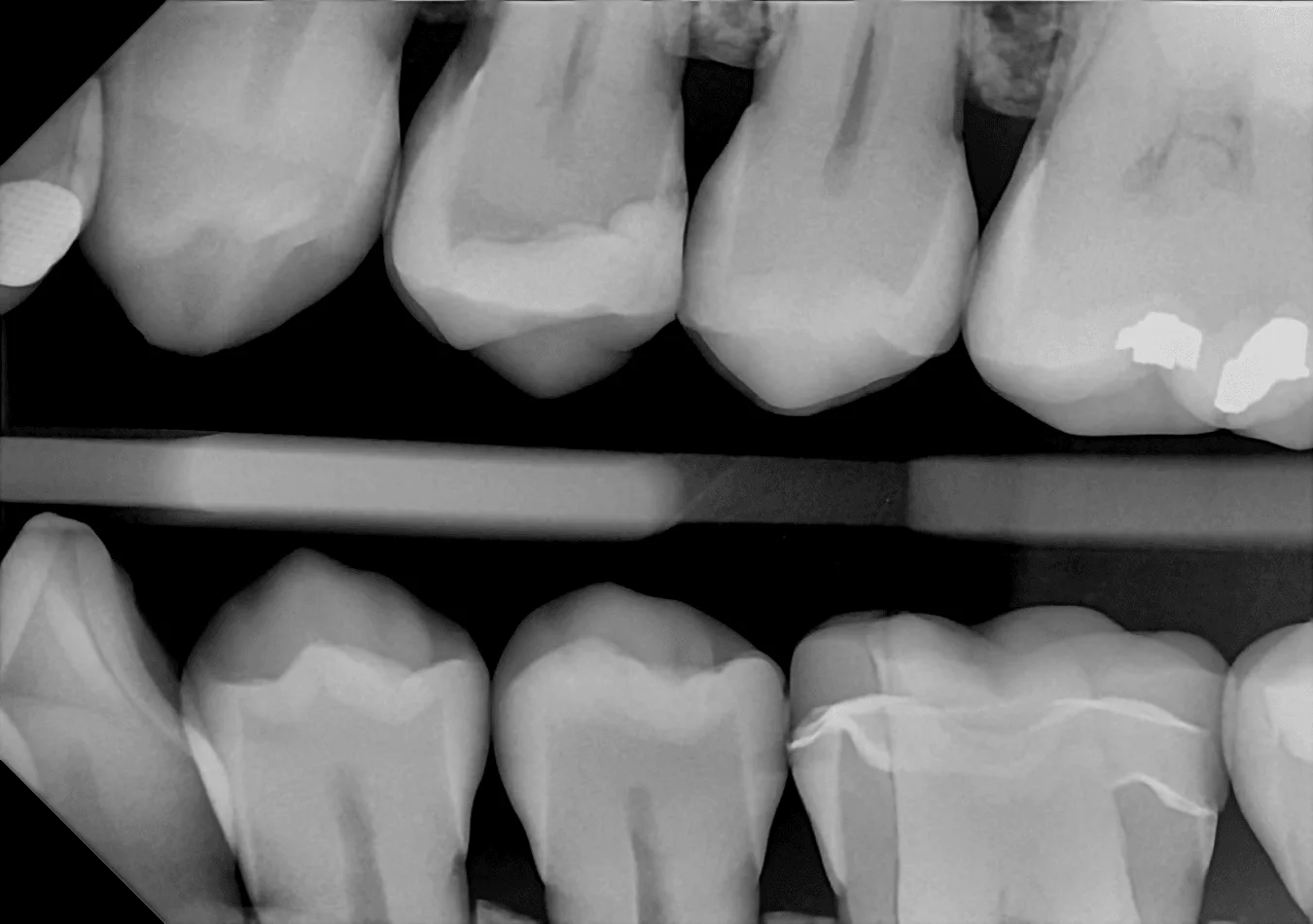
The difference starts inside the sensor
A conventional indirect-conversion sensor uses a scintillator to turn X-ray energy into visible light. A light-sensitive detector then converts that light into an electrical signal. Depending on the design, a fiber-optic plate sits between those layers. Light can spread along that path, reducing how distinctly the system records fine structures.
DC-Air uses a single-crystal silicon detector that converts X-ray energy directly into electrical charge. It has no scintillator and no fiber-optic plate. The design removes that intermediate light-conversion step. FTG’s technology documentation describes the detector and its published performance.
| What you’re comparing | Conventional indirect conversion | DC-Air direct conversion |
|---|---|---|
| Conversion path | X-rays → light → electrical charge | X-rays → electrical charge |
| Scintillator | Part of the conversion path | No scintillator |
| Fiber-optic plate | Used in some sensor designs | No fiber-optic plate |
| Starting image for a demo | Identify the applied processing | Start with sharpening off |
There’s an easy terminology trap here: CMOS and direct conversion describe different things. A sensor can be both. CMOS refers to the electronics; direct conversion tells you how the X-ray becomes the signal. Ask about the conversion path when you’re comparing designs.
Look closely at the comparison
The anterior comparison below shows why we ask you to start with the unsharpened capture. Follow the boundaries around the restoration and the tonal transitions in the surrounding tooth. Take enough time to see what each image lets you distinguish.
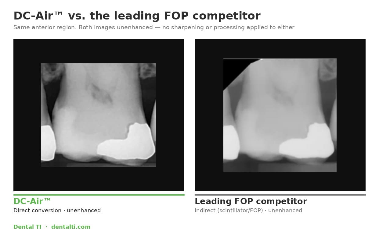
Pick a small area and stay with it. Trace the edge of the restoration. Look at whether adjacent tones remain distinguishable as you enlarge the view. Notice the texture within the tooth as well as the outline around it. A stronger outline alone doesn’t tell you how faithfully the underlying detail was recorded.
You can also open the interactive DC-Air comparison. Move the divider across the same area instead of trying to remember what was on the previous slide. The page includes a radiograph viewer so you can inspect more than one selected example.
These images give you a place to start asking questions. Your purchase decision should include a review of the files, their processing settings, and the software your team will use.
What sharpening changes
Sharpening increases local contrast around edges. It can help a clinician inspect an image, and a practice may prefer a particular amount of it. But a processing setting doesn’t tell you what the detector originally captured.
That’s why the order of a demonstration matters. Look at the unsharpened image first. Then change the settings and see what becomes easier to inspect, what becomes more pronounced, and whether distracting texture or halos appear.
DC-Air starts with an unsharpened capture. If your office wants additional sharpening, AccuSharp™ is available in the DC-Air TWAIN driver. Our online radiograph viewer demonstrates that control alongside brightness and contrast. AccuSharp starts off; Reset returns you to the source image.
When we say “captured, not synthesized,” we’re talking about that starting image. Optional processing remains a choice the office can make after seeing it.
Read the MTF number with its units
MTF, or modulation transfer function, describes how well an imaging system preserves contrast at different levels of fine detail. Spatial frequency is commonly expressed in line pairs per millimeter. As the line pairs get closer together, they become harder for the system to distinguish.
FTG publishes DC-Air MTF values of greater than 70% at 5 lp/mm and greater than 40% at 10 lp/mm. Those are manufacturer-reported measurements. Keep the frequency beside each percentage: “70% MTF” on its own leaves out the level of detail being measured.
For a buyer, the useful next question is how the comparison was measured. Ask whether the figures describe the detector or a processed image, which settings were used, and whether the systems were tested under comparable conditions. Pixel size alone won’t answer those questions.
MTF also has a specific job. It characterizes contrast transfer; it doesn’t tell you the percentage of cavities a clinician will detect. Exposure, positioning, noise, processing, and the clinical task still matter. Use the measurement to make the demonstration more demanding, then inspect the images.
Make the demo earn the purchase
Bring the name of your current sensor and imaging software. Have the team member who takes most of your radiographs join the conversation. They’re the person who can tell you whether the acquisition workflow will fit a busy morning.
Here’s what I’d ask to see before making a decision:
- The starting image. Ask which corrections and enhancement settings are already applied. If a setting can’t be disabled, have the demonstrator explain it. “Default” and “unprocessed” aren’t interchangeable.
- A fair comparison on the same display. Match the viewing size and inspect the same region. Ask how the example images were acquired and whether the exposure and geometry are comparable. Use existing comparison material or a suitable test object to work through the acquisition settings.
- The adjustments your practice actually uses. Work through brightness, contrast, and optional sharpening. See how easily the team can return to the starting view.
- The complete acquisition workflow. Check the software integration, holder setup, and how the image reaches the patient record. A useful comparison includes what the assistant does before the image appears.
Keep a short record of what you saw and what remains to be confirmed. It gives everyone involved in the purchase something more useful to discuss than which demonstration looked impressive.
Decide what the change is worth in your practice
If you’re already satisfied with the detail you can inspect and the way your team captures images, ask what a replacement would improve. A newer sensor needs to earn its place.
If your concern is diagnostic image accuracy, spend the demonstration on the native captures and the conversion path. If cable handling and recurring repairs are driving the purchase, put the wireless workflow and your actual service costs alongside that evaluation. The five-year sensor cost guide can help with that part of the decision.
DC-Air is worth a close look because the design changes both the capture and the physical workflow. You can examine those differences before committing to a system.
The complete DC-Air kit is $6,995
That price includes the DC-Air™ sensor, charging dock, USB-C cable, complete Zero Profile® holder kit, and a TWAIN license for one network with unlimited PCs. Installation, software integration, team training, expert support, and a two-year manufacturer warranty are included.
Complete kit: $6,995 with current special pricing. Sales tax is excluded. See the kit details and shipping terms, then bring us the software and workflow questions you want answered before ordering.
Compare DC-Air with your current setup. Tell us the sensor and imaging software you use, and what you’d like to improve. We’ll help you inspect the images and confirm how it would work in your practice.